4.1.3. Configuration Data – BoltLengthCalculation.json
4.1.3. Configuration Data – BoltLengthCalculation.json
The bolt calculation engine reads its rules from
the file "BoltLengthCalculation.json," which
is located in the "Resources" folder of the add-in. This file contains
six sections:
For comfortable editing of the configuration, the command
"Load Data" is available (see Section 4.1).
This imports an Excel workbook (.xlsx), in which each of the
sections mentioned above is mapped as a separate tab. In
this way, all values can be maintained in a familiar
spreadsheet environment before being converted into the internal
JSON format.
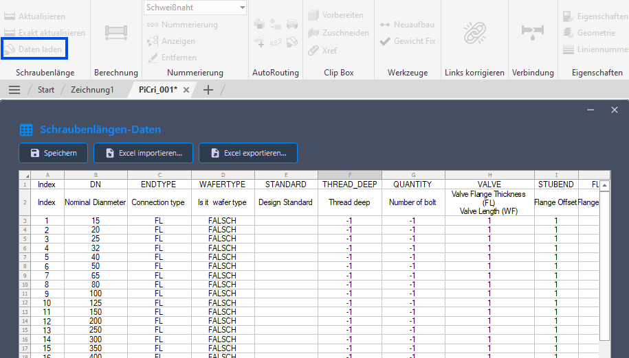
"Formula" Section
The "Formula" section defines the lookup rules that assign each bolt set to a calculation formula. Each row represents a rule and contains the following columns:
Standard end codes are FL
(Flange), WF (Wafer), and LUG (Lug-type valve
with threaded blind holes). In addition, any
project-specific end codes can be added as additional lines to
represent individual connection types.
Note on multiplier columns: The
following multiplier columns (VALVE,
STUBEND, FLANGE, NUT,
WASHER, ADDITIONAL) indicate how
often the associated contribution occurs per connection. A value
of 0 means that the contribution is not taken into account;
a value of 1 or higher means n-fold
consideration. For a wafer connection (WF), there is only
one connection; accordingly, the component length or
flange thickness is included once.
Behavior for missing components: If a component referenced in the
formula is not present in a specific connection
(e.g., a weld neck via the STUBEND column), no error is
triggered. The corresponding contribution is simply omitted from the sum.
This allows the same formula row to be used for different connection variants.
| Column | Description |
|---|---|
| DN | Nominal diameter of the bolt set (numeric, in mm). Used to match the nominal diameter of the bolted joint. |
| ENDTYPE | Connection type (e.g., FL for flange, WF for
wafer). Matched to the main connection conditions of the bolted joint. |
| STANDARD | Design standard filter (e.g., API 600). If
specified, the rule only applies to bolt sets connected to valves with
a matching DesignStd property. If empty, the rule applies regardless of the standard. |
| WAFERTYPE | Set to TRUE for wafer-type connections
(through bolts). Wafer bolts span both the flanges
and the valve body and are calculated using a special
aggregation method. |
| THREAD_DEEP | Additional thread engagement depth (mm) added to the bolt length. |
| QUANTITY | Number of bolts in the set. If this value is greater than 0,
it updates the "NumberInSet"
property of the bolt. |
| VALVE | Multiplier for the valve contribution. If a value greater than 0
is set, the flange thickness of the connected
valve is included in the calculation and multiplied by this factor. |
| STUBEND | Multiplier for the stub end's contribution. If this value is greater
than 0, the flange offset of the connected
stub end is multiplied by this factor. |
| FLANGE | Multiplier for the flange contribution. The flange thickness
of the connected flange is multiplied by this factor and
added to the bolt length. |
| NUT | Number of nuts. The nut thickness (from the nut table) is multiplied by this value. |
| WASHER | Number of washers. The washer thickness (from the "Washer" table) is multiplied by this value. |
| ADDITIONAL | Number of additional length elements. The value for the additional length (from the "AdditionalLength" table) is multiplied by this factor. |
| ROUND | Rounding direction: UP rounds to the next larger
standard length; DOWN rounds to the previous smaller
standard length. |
| SIZE_DESCRIPTION | Template for the "PartSizeLongDesc" property. Use
&&& as a placeholder for the bolt size and
@@@ as a placeholder for the bolt length. Example:
Hex Bolt &&& x @@@ |
| FAMILY_DESCRIPTION | Template for the "PartFamilyLongDesc" property. Same placeholders as
for SIZE_DESCRIPTION. |
"Nut" Section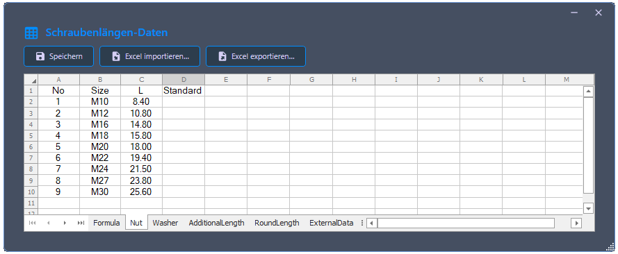
Defines nut thicknesses by bolt size and standard.
| Column | Description |
|---|---|
| Size | Bolt size designation (e.g., M16,
M20). |
| L | Nut thickness in millimeters. |
| Standard | The bolt standard to which these nut specifications refer
(matched with BoltCompatibleStd). |
"Washer" Section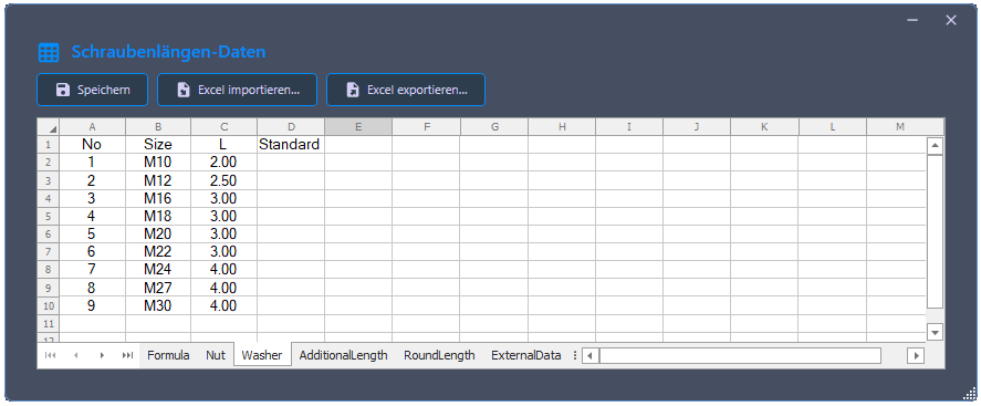
Defines washer thicknesses by bolt size and standard.
| Column | Description |
|---|---|
| Size | Bolt size designation. |
| L | Washer thickness in millimeters. |
| Standard | The bolt standard to which this washer data refers. |
"AdditionalLength" Section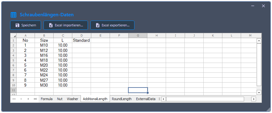
Defines an additional length contribution per bolt (e.g., insertion allowance for gaskets).
| Column | Description |
|---|---|
| Size | Bolt size designation. |
| L | Additional length in millimeters. |
| Standard | The bolt standard for which this additional length applies. |
"RoundLength" Section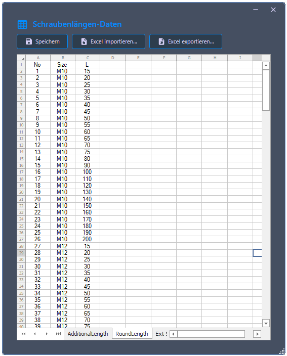
Defines the discrete set of valid (commercially available) bolt lengths for rounding.
| Column | Description |
|---|---|
| Size | Bolt size designation. |
| L | A valid bolt length in millimeters. |
Multiple entries per size are expected (one per available length). The system sorts these in ascending order and selects the appropriate value according to the rounding direction.
Note on extensibility: The Nut,
Washer, AdditionalLength and
RoundLength can be extended with additional
bolt sizes, standards, and lengths as needed. This allows the calculation to
be adapted to different project-specific requirements –
for example, if a different protrusion than the preset 10 mm
is desired or if further bolt sizes are to be supported.
"ExternalData" Section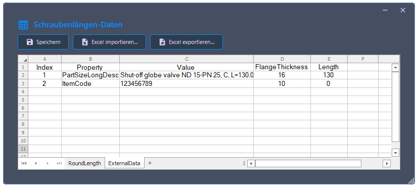
Defines external component data (especially flange thicknesses and component lengths) for components where the corresponding properties are not directly maintained in the 3D model. This is necessary, for example, for custom components or for catalogs without stored flange thickness properties.
Each row assigns to any Plant 3D property (e.g.,
PartFamilyLongDesc, PartSizeLongDesc, or
ItemCode) in combination with a specific value, the
associated flange thickness and – if relevant – the component length.
These values are used in the calculation as soon as the
bolt data source "From external
data" is selected in the drawing selection.
| Column | Description |
|---|---|
| Property | Name of the Plant 3D property through which the assignment is made (e.g.,
PartFamilyLongDesc). |
| Value | Specific property value by which the component is identified. |
| FlangeThickness | Flange thickness in millimeters to be included in the calculation for this component. |
| Length | Component length in millimeters. Primarily needed for wafer components;
for pure flange connections, the value can be 0. |
During the calculation, the program first searches the external data. If it finds an entry with a matching Property/Value combination on the component, the stored values are used. Otherwise, the component properties from the model are used.