3. User Interface Guide (UI)
3. User Interface Guide (UI)
Upon loading, PiCri adds its own PiCri tab to the AutoCAD Ribbon. The tab includes the following panels, from left to right:
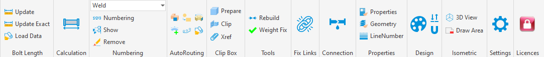
The order of the panels follows the Ribbon from left to right, as shown in the table below.
| Panel | Buttons | Purpose |
|---|---|---|
| Bolt Length | Refresh, Precise Refresh, Load Data | Bolt length calculation and data import |
| Calculation | Total Pipe Length | Pipe length report with optional surface and volume (Excel export) |
| Annotation | Mode (Weld / Spool / Part), Numbering, Display, Remove | Pipeline numbering and annotation |
| AutoRouting | Auto Route, Convert, Mirror, Place Elements, Place Fasteners, Load Data | Automated routing of conduits and placement of auxiliary/fastening components |
| Clip-Box | Prepare, Cut, XRef | 3D model clipping and XRef-related visibility/snap control |
| Tools | Rebuild Connection, Weight Adjustment | Connection repair and weight correction |
| Repair Links | Repair Component Link | Restore links between model components and Plant 3D specification |
| Connection | Check Unconnected Components | Connection integrity checks within the model |
| Properties | Match Properties, Match Geometry, Line Number | Transfer line properties and geometry; browse line numbers |
| Design | Assign Color, High/Low Point, Pipe Sag | Temporary coloring and checks on piping design |
| Isometric | 3D View, Draw Area | Viewport area on the isometric and 3D view placement |
| Settings | Settings | Application configuration |
| Licenses | Licenses | License Management |
Each panel and its functions are described in detail in the following sections. Section 4.9 summarizes the "Calculation" command. Other sections cover Clip-Box, Tools, Repair Links, Connection, Properties, Design, and Isometric.