3.3. Module 3 (P3D)
In this article, you will get an overview of the user interface and the basic functions of Module 3 (P3D). Knowledge of the interface structure is essential for efficient navigation and command execution within the software.
Prerequisites
Ensure that Module 3 (P3D) is correctly installed and licensed before you begin operation.
User Interface Overview
The interface is clearly structured and divided into three main areas:
- Navigation menu on the left side
- Status bar at the top right
- Command panel on the right side
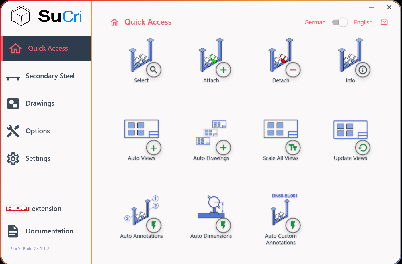
The expected result is a fully loaded user interface of the respective manufacturer.
Step-by-Step Instructions
1. Using the navigation menu
Use the menu on the left side to switch between the different functional groups. Click on a group so that the available commands in the command panel adjust dynamically.
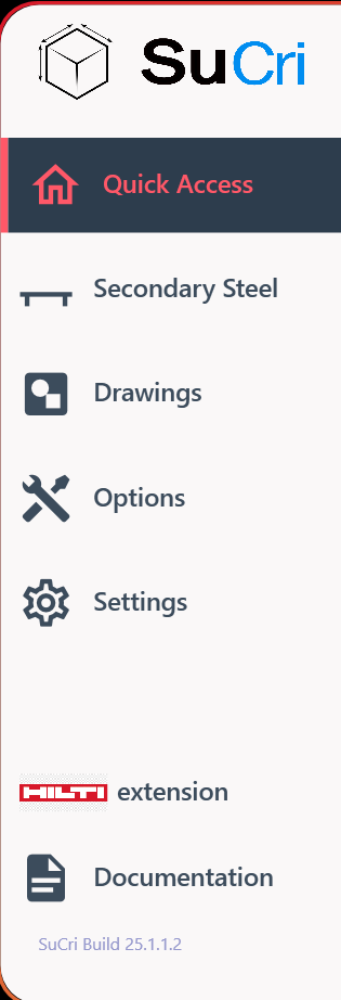
Result: The icons in the right area change according to your selection.
2. Operating the status bar
In the status bar, you will find information about the currently active panel. In addition, you can switch the language here or contact support directly via the email icon.

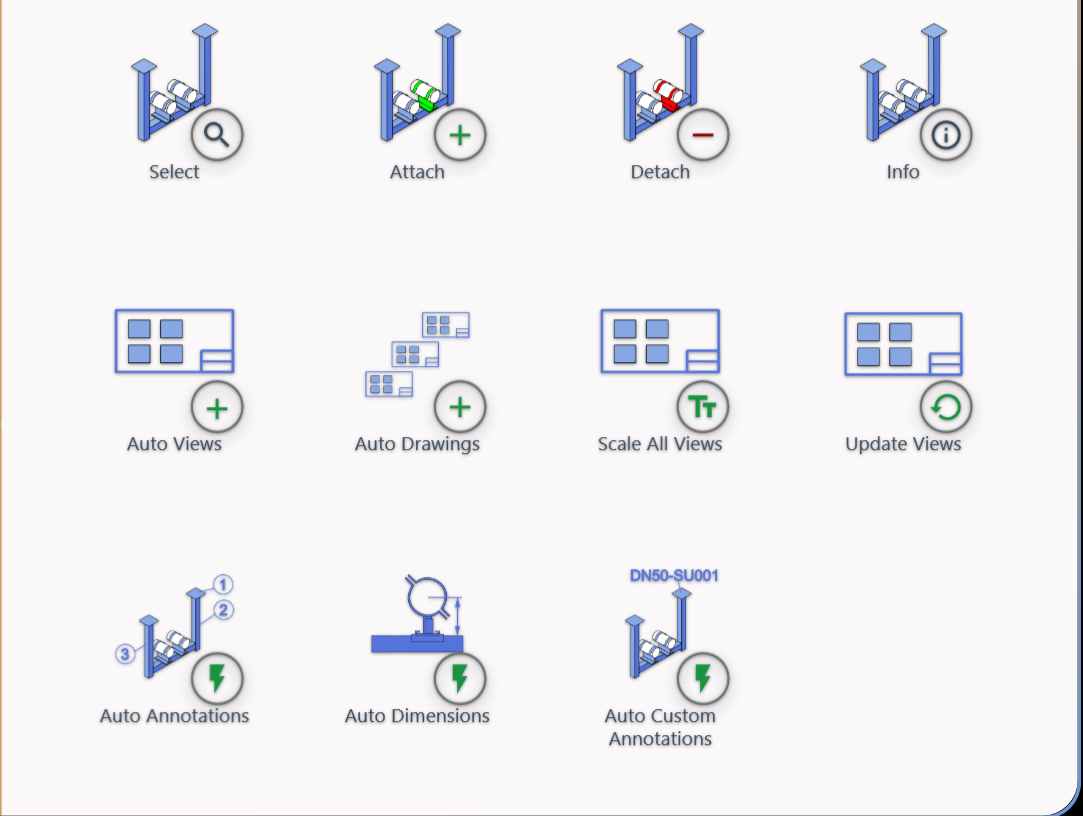
3. Using the command panel
In the command panel, select the specific actions you need for your current planning. These commands always refer to the group selected in step 1.
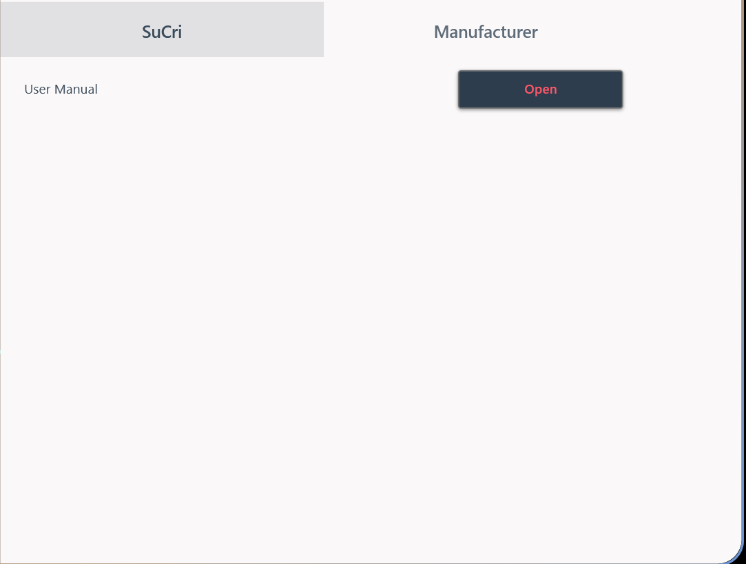
4. Accessing documentation
Open the documentation panel to access further resources and links, such as the integrated knowledge base.
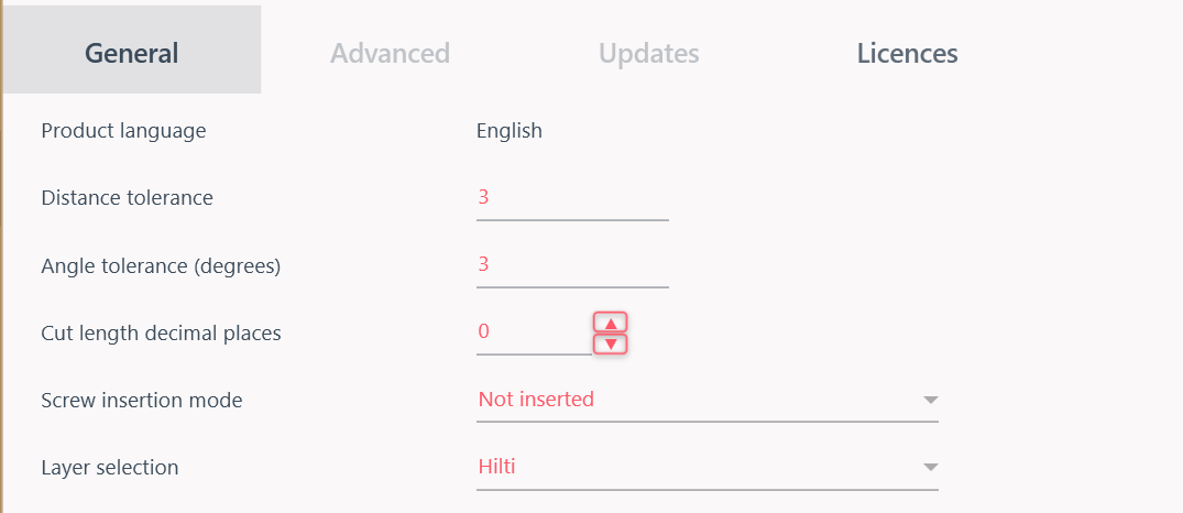
5. Adjusting settings
Navigate to the settings panel to make specific configurations and parameters for your work environment.
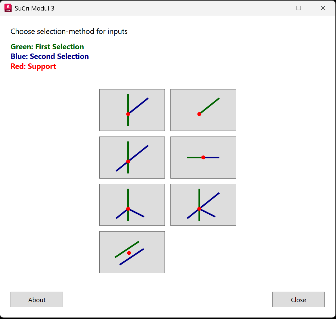
6. Placing connections
Use the connections dialog to place connections in your drawing. Here you will find all relevant buttons for placing local elements.
Important Notes
- Manufacturer Skins: Each manufacturer has its own interface color. Note, however, that the structural setup remains identical for all manufacturers.
- Dynamics: The command panel adjusts immediately when you select a different group in the navigation menu.