4.11. 3D View to Isometric, Features and Functionalities
On this page
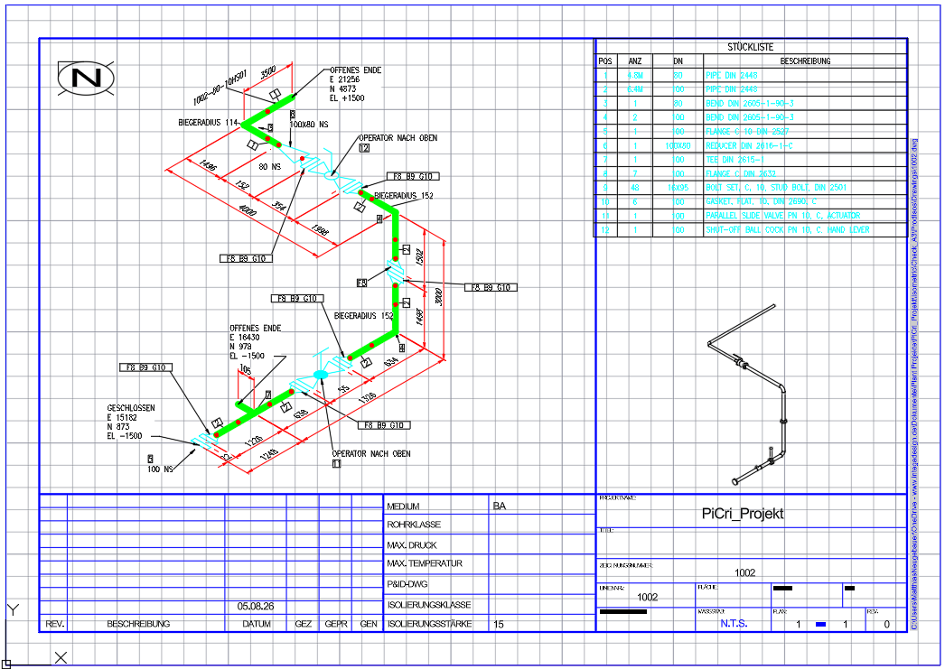
Places a 3D wireframe representation of the pipeline in a defined area on the isometric drawing. This facilitates the spatial understanding of complex pipeline routes and provides additional visual value, especially for workshop fabrication.
Ribbon button: Isometric > 3D View
Command: PiCriIso3DView
Preparation in the ISO Template (DWT): For the 3D view to be displayed on the isometric, a placement area must be defined once in the ISO DWT template. Use the command "Draw Area" to create a frame in the template where the 3D view should later appear. Then save the DWT. All isometric drawings generated with this template are now available for the 3D view function.
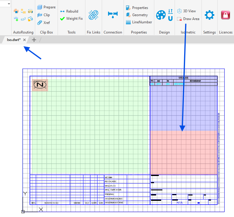
Procedure after ISO Generation:
- Generate the isometric drawings as usual. After generation, the placement area on the ISO is initially empty.
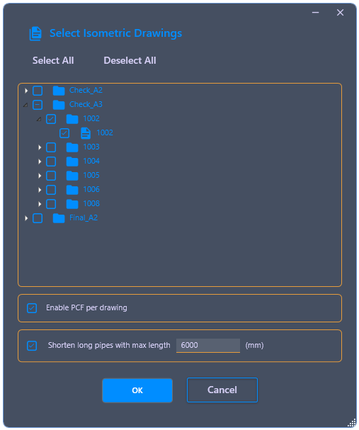
- Start the command "3D View". In the dialog, select the isometric drawings that should receive a 3D view.
- Select the desired display style and the corresponding ISO style number.
- If necessary, activate the option "Shorten long pipes". This option is useful if the pipeline contains very long straight sections that would otherwise exceed the placement area. Excessively long pipes are then displayed as compressed, but remain visually recognizable.
- Confirm with OK. PiCri reads the 3D model, generates a wireframe variant of the pipeline, and places it in the previously defined area on the isometric.