2.2.1. Module 1, Installation guide
On this page
2.2.1. Module 1, installation and configuration
In this article you will learn how to correctly install Module 1 and integrate it into your project. Careful setup of the symbol files and SKEY mappings is decisive for error-free isometric output.
Prerequisites
- The installation program for Module 1 is available locally.
- An existing AutoCAD Plant 3D project is available.
- A text editor (e.g. Notepad) is installed for editing XML files.
Step-by-step guide
-
Step 1: Run the installation program
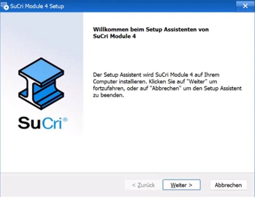
Start the supplied installation program and follow the instructions on the screen.
-
Step 2: Select extensions
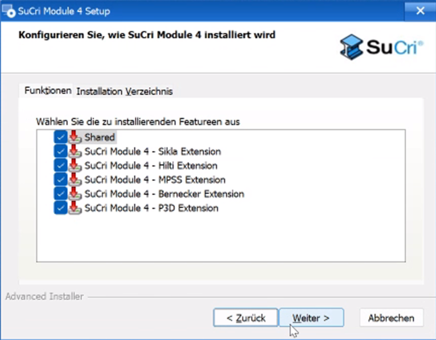
In the dialog, select the desired Extensions that you want to install together with the module.
-
Step 3: Set the content path
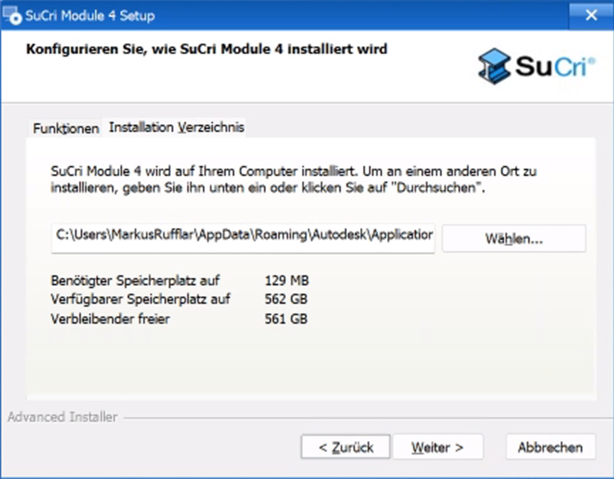
Set the correct content path for the installation to ensure that all data is stored in the correct directory.
-
Step 4: Accept the terms of use
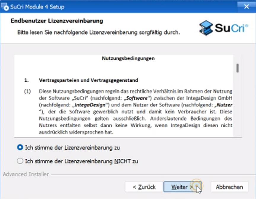
Read and accept the terms of use in order to be able to continue with the process.
-
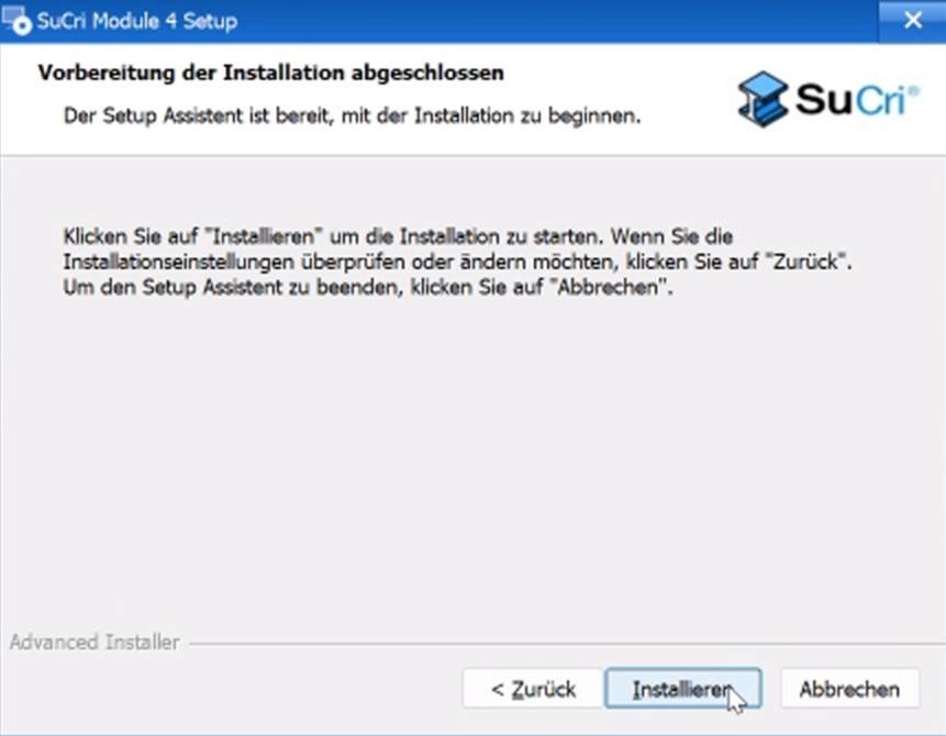
Step 5: Start the installation
Click the button to start the installation.
-
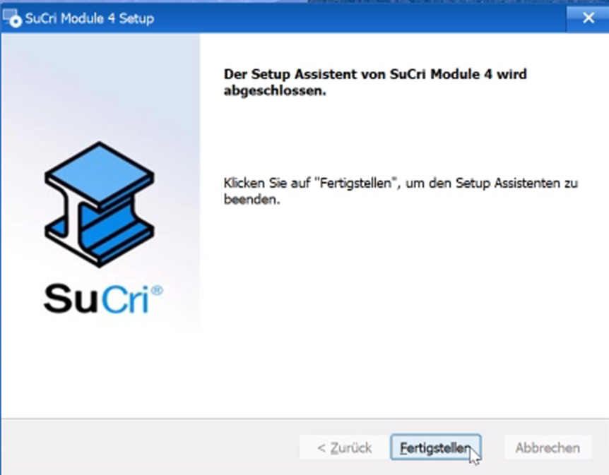
Step 6: Complete the installation
After the process is complete, click Finish. The bundle was automatically installed in the path
C:\Users\Username\AppData\Roaming\Autodesk\ApplicationPlugins. -
Step 7: Prepare IsoSymbolStyles.dwg
Open the file
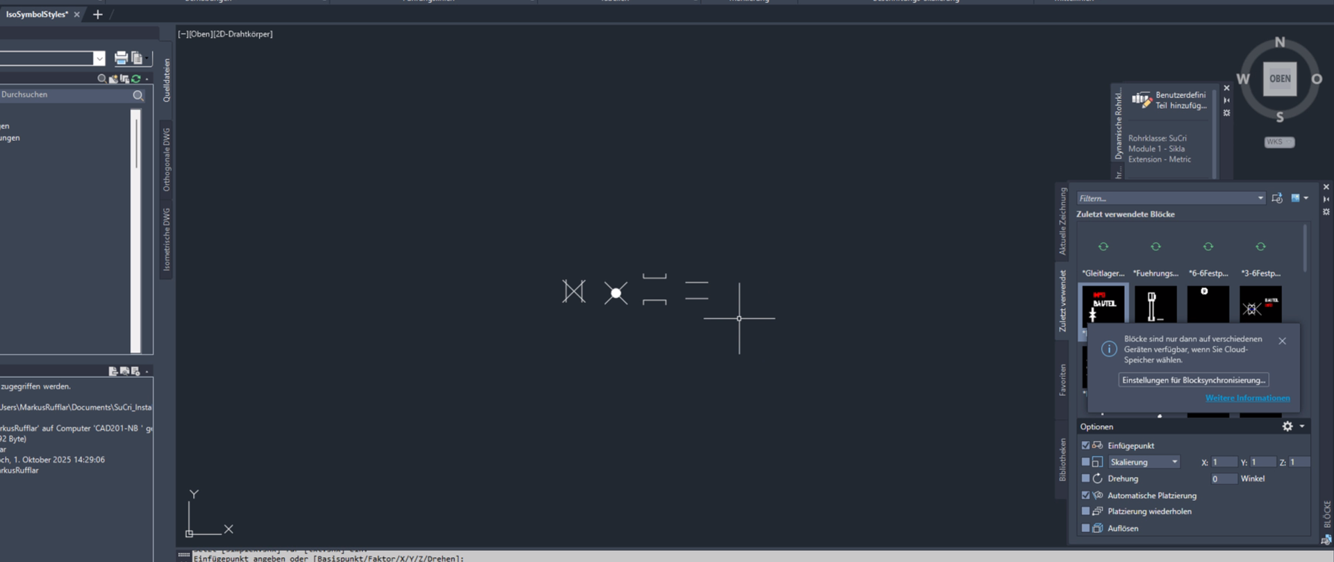
IsoSymbolStyles.dwgfrom the Isometric folder of your project. In Windows Explorer, navigate to the pathC:\AutoCAD Plant 3D 202X Content\CPak IntegaDesign\IsoSymbols. Drag the four contained symbol DWGs individually into your open drawing (scale = 1, rotation = 0). Delete the placed elements again afterwards; the block definitions remain stored in the file. Save and close the file. -
Step 8: Configure the SKEY mapping
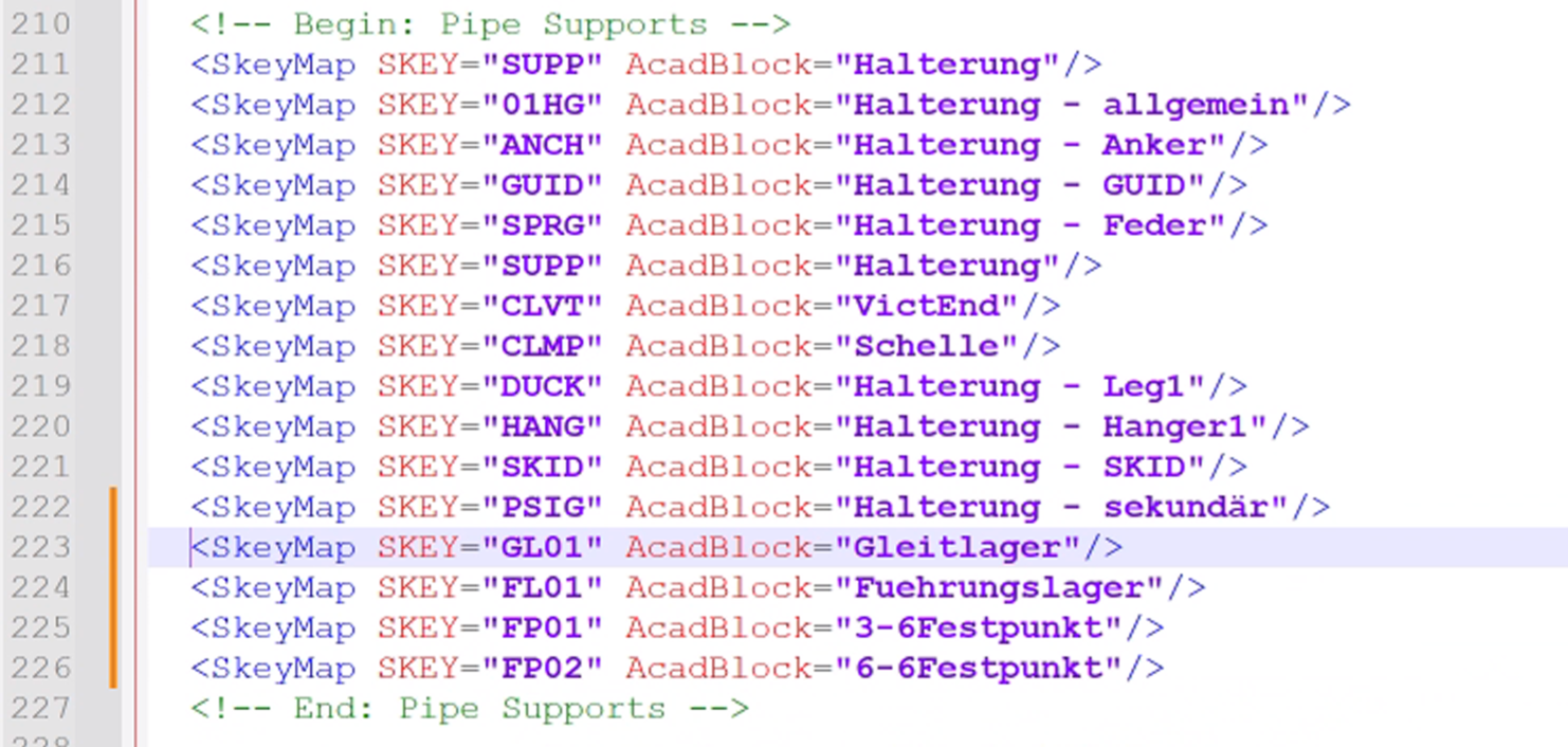
Open the
IsoSkeyAcadBlockMap.xmlin your project folder with a text editor. Copy the<SkeyMap …>entries from the supplied XML file in the IsoSymbols folder and insert them into the "Supports" section. Save and close the file. -
Step 9: Import pipe classes
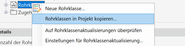
Start AutoCAD Plant 3D and import the supplied pipe class via the Project Manager. You can now start working in the module.
Important notes
- Avoid duplicates: Make sure that the SKEY designations do not yet exist in your project, since duplicate entries cause errors in the isometric.
- Alternative loading method: Instead of by drag-and-drop, the symbol files can also be loaded via the AutoCAD Design Center.
- Adaptability: Based on the supplied catalog, you can create your own pipe classes at any time or adapt existing ones to your standards.
Troubleshooting
- If the isometric symbols are not displayed correctly, check in the
IsoSymbolStyles.dwgwhether the block definitions actually remained in the file after the geometry was deleted. - In case of problems with the SKEYs, make sure that the XML syntax was not damaged when copying (all tags must be closed correctly).