4.2.4. Support (SuCri2AutoSelectSupport)
On this page
Overview
With the Support function (SuCri2AutoSelectSupport) you automatically place a support for a pipe on a beam profile in AutoCAD Plant 3D. You only select the profile and the pipe; SuCri calculates the distance and offers the matching supports from the pipe spec for selection. You can replace an existing support in the same way.
Where can I find the function?
"SuCri" tab > "Module 2" panel > manufacturer button of your licensed catalog > Dashboard > Quick Access (or Turbo Tools) > Support.
Alternatively, in the SuCri tool palette under Single Placement > Support. The palette has no ribbon button of its own; you open it in the dashboard via the pushpin icon in the title bar ("Pin to tool palette"). The SuCri2AutoSelectSupport command can also be entered directly on the command line.
Plant 3D™ command
Property | Value |
| Command | SuCri2AutoSelectSupport |
Icon | |
| Ribbon | SuCri > Module 2 > manufacturer button > Dashboard > Quick Access > Support |
| Tool palette | Single Placement > Support |
| Keyboard shortcut | not assigned |
Video
How it works in detail
Start the function
Start Support via the dashboard, the tool palette or the command line.
Expected result: The command line shows "Select Steel Structure:".
Select the beam profile
Click the beam profile (e.g. U-channel or I-beam) to which the support is to be attached. The profile may also be located in an xref.
Expected result: The profile is highlighted and the command line prompts "Select Support/Pipe:".
Select the pipe or an existing support
Click the pipe to place a new support. Click an existing support to replace it.
Select the support
SuCri calculates the distance between pipe and profile and lists the matching supports on the command line ("Select available support:"). Press Enter to accept the suggestion, or select another option. Press Esc to cancel.
Expected result: The support is placed in the model.
Check and finish
Visually check the alignment of the components and save your drawing.
When an existing support is replaced, SuCri transfers the properties entered in the Properties kept when replacing a support setting.
Settings
"SuCri" tab > "Settings" panel > Settings (command SuCriSettings), "Module 2" area, "General" tab, "Turbo Tools" group:
- Support info shown in Turbo Tools (selection list, default value: PartSizeLongDesc): Which designation the list on the command line shows (PartFamilyLongDesc, PartSizeLongDesc or ShortDescription).
- Properties kept when replacing a support (comma-separated list, default value: Tag, SuNo): Properties that are transferred from the replaced support to the new one.
- Max. pipe slope (°) (number, default value: 3): Pipes with a steeper slope do not receive a support.
- Colour pipe red when no support is found (On/Off, default value: enabled): Colors the pipe red if no suitable support is found.
- Allow reverse pipe shoe (On/Off, default value: disabled): Allows pipe shoes in reversed orientation.
Application examples
Example 1: Supporting a pipe on a cross beam
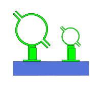
You select the cross beam, then the pipe above it, and accept the suggested support with Enter.
Example 2: Changing the support type
A placed support is to be replaced by a different type. You select the beam and then the existing support; with the default setting, the tag and SU number are retained.
Tips and best practices
- Order: Make strictly sure to select the structural profile first and then the pipe or support.
- Project standards: After creation, check in the Properties palette whether the layers and object styles comply with your standards.
- With clamp: If a clamp is to be placed at the same time, use Support+Clamp.
- Multiple pipes: For many pipes on one structure, use Support [x].
Troubleshooting
- "Invalid steel structure": The object selected in the first step is not a valid profile.
- "Cannot find suitable support. Make sure the distance is valid.": No support of the pipe spec fits the distance between pipe and profile. If the Colour pipe red when no support is found setting is active, the pipe is marked red.
- "To use ... please move the pipe ..." or "... far from profile ...": The desired support only fits after the pipe has been moved by the specified amount.
- "Pipe slope = ... degree > max slope allowed (...)": The pipe is steeper than set in Max. pipe slope (°).
- "Please select only support type": In the second step, neither a pipe nor a support was selected.
Related articles
- Clamping system, then places the clamp on the support.
- Support + Clamping system, places support and clamp in one pass.
- Support [x], places supports for multiple pipes.
- Attaching, combines components into an assembly and assigns the SU number.
Copyright © 2026 by IntegaDesign GmbH. All Rights Reserved.